AD 47-06-01
Applicability
| Type | Manufacturer | Model | Details |
|---|---|---|---|
| aircraft | Swift Museum Foundation, Inc. | GC-1A | Airworthiness Directives; GLOBE Models GC-1A and GC-1B Aircraft. |
| aircraft | Swift Museum Foundation, Inc. | GC-1B | Airworthiness Directives; GLOBE Models GC-1A and GC-1B Aircraft. |
Unsafe Condition
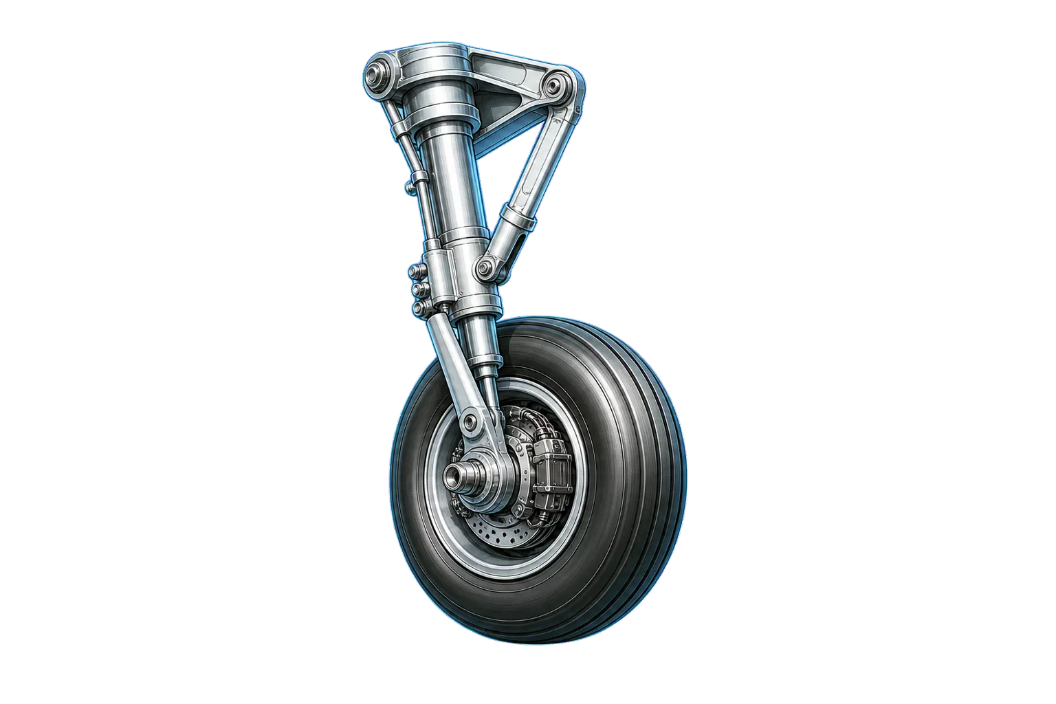
The main landing gear retraction system may have improper adjustments in the side brace down stop position, down lock plunger clearance, limit switch plunger depression, and emergency extension cable turnbuckle settings, leading to potential gear malfunctions or failure during operation.
AI-generated summary from the source AD text. Verify against the official source before acting.
Required Actions
Inspect main landing gear retraction system adjustments for side brace position, down lock plunger clearance, limit switch plunger depression, and emergency extension cable turnbuckle settings. Ensure adjustments meet specified tolerances as outlined in Globe Customer Service Maintenance Bulletin No. 7.
AI-generated summary from the source AD text. Verify against the official source before acting.
Compliance Time
prior to April 1, 1947, and upon each 100 hours operation thereafter
AI-generated summary from the source AD text. Verify against the official source before acting.
Affected Aircraft
Swift Museum Foundation, Inc. Models GC-1A and GC-1B Aircraft
AI-generated summary from the source AD text. Verify against the official source before acting.
Federal Register Abstract
Main Landing Gear Retraction System
Applicability Source Text
Show captured applicability text from the source AD
AD Final Rules - DRS_47-06-01.html
Copy URL
Print/Save as PDF
Document Versions
 Feedback
Details
AD Number:
47-06-01
Document Type:
AD Final Rules
Docket Number:
Unknown
Subject Heading:
Airworthiness Directives; GLOBE Models GC-1A and GC-1B Aircraft.
Subject:
Main Landing Gear Retraction System
Status:
Current
Citation:
This information is not available.
Citation Publish Date:
Effective Date:
Make:
Swift Museum Foundation, Inc.
Model:
GC-1A | GC-1B
Product Type:
Aircraft
Product Subtype:
Small Airplane
Affected AD:
Superseded AD:
Affected By:
Superseded By:
Service/Office:
Office of Primary Responsibility:
CFR Part Reference:
Part 39
Comments:
AIRWORTHINESS DIRECTIVES FINAL RULES: 47-06-01
CITATION:   This information is not available.

PAGE NUMBER:

DOCKET NUMBER:   Unknown

AMENDMENT:

AD NUMBER:   47-06-01

SUBJECT HEADING:   Airworthiness Directives; GLOBE Models GC-1A and GC-1B Aircraft.

ACTION:

SUMMARY:

DATES:

ADDRESSES:

FOR FURTHER INFORMATION CONTACT:

SUPPLEMENTARY INFORMATION:

REGULATORY TEXT:   47-06-01 GLOBE: (Was Service Note 1 of AD 766-5.) Applies to Models GC-1A and GC-1B Aircraft.

To be accomplished prior to April 1, 1947, and upon each 100 hours operation thereafter.

Inspect main landing gear retraction system to determine that adjustments are as follows:

(1) When the side brace is against the down stop the middle joint should be 1/8 inch to 1/4 inch above dead center (3/16 inch to 5/16 inch if measured from edges of links in accordance with Globe Customer Service Maintenance Bulletin No. 7).

(2) When the side brace is against the down stop and the down lock plunger is fully extended, covering at least 1/2 of the adjustment screw head, the clearance between the plunger and the screw head should be from 0.001 inch to 0.005 inch.

(3) When the side brace is against the down stop the limit switch plunger should be depressed approximately 1/32 inch beyond the cutoff point.

(4) The turnbuckle in the emergency extension cable should be adjusted so that on manual extension of the gear both down locks operate before the handcrank has been wound to the full down position. After it has been determined that the turnbuckle adjustment is satisfactory in this respect it should be determined also that with the handcrank wound to the full up position the cable length is sufficient to permit the up limit switches to cut off.

(Globe Customer Service Maintenance Bulletin No. 7 covers this same subject.)

FOOTER:
Document Text
Show stored source text (verify against official source)
AD Final Rules - DRS_47-06-01.html
Copy URL
Print/Save as PDF
Document Versions
 Feedback
Details
AD Number:
47-06-01
Document Type:
AD Final Rules
Docket Number:
Unknown
Subject Heading:
Airworthiness Directives; GLOBE Models GC-1A and GC-1B Aircraft.
Subject:
Main Landing Gear Retraction System
Status:
Current
Citation:
This information is not available.
Citation Publish Date:
Effective Date:
Make:
Swift Museum Foundation, Inc.
Model:
GC-1A | GC-1B
Product Type:
Aircraft
Product Subtype:
Small Airplane
Affected AD:
Superseded AD:
Affected By:
Superseded By:
Service/Office:
Office of Primary Responsibility:
CFR Part Reference:
Part 39
Comments:
AIRWORTHINESS DIRECTIVES FINAL RULES: 47-06-01
CITATION:   This information is not available.

PAGE NUMBER:

DOCKET NUMBER:   Unknown

AMENDMENT:

AD NUMBER:   47-06-01

SUBJECT HEADING:   Airworthiness Directives; GLOBE Models GC-1A and GC-1B Aircraft.

ACTION:

SUMMARY:

DATES:

ADDRESSES:

FOR FURTHER INFORMATION CONTACT:

SUPPLEMENTARY INFORMATION:

REGULATORY TEXT:   47-06-01 GLOBE: (Was Service Note 1 of AD 766-5.) Applies to Models GC-1A and GC-1B Aircraft.

To be accomplished prior to April 1, 1947, and upon each 100 hours operation thereafter.

Inspect main landing gear retraction system to determine that adjustments are as follows:

(1) When the side brace is against the down stop the middle joint should be 1/8 inch to 1/4 inch above dead center (3/16 inch to 5/16 inch if measured from edges of links in accordance with Globe Customer Service Maintenance Bulletin No. 7).

(2) When the side brace is against the down stop and the down lock plunger is fully extended, covering at least 1/2 of the adjustment screw head, the clearance between the plunger and the screw head should be from 0.001 inch to 0.005 inch.

(3) When the side brace is against the down stop the limit switch plunger should be depressed approximately 1/32 inch beyond the cutoff point.

(4) The turnbuckle in the emergency extension cable should be adjusted so that on manual extension of the gear both down locks operate before the handcrank has been wound to the full down position. After it has been determined that the turnbuckle adjustment is satisfactory in this respect it should be determined also that with the handcrank wound to the full up position the cable length is sufficient to permit the up limit switches to cut off.

(Globe Customer Service Maintenance Bulletin No. 7 covers this same subject.)

FOOTER:
Source: Official FAA Source ↗
Retrieved: Apr 8, 2026
Rights: U.S. Government Public Domain
This site is not affiliated with or endorsed by the FAA. Always verify with official sources.
Related Airworthiness Directives
47-25-07
final ruleAirworthiness Directives; Globe Models GC-1A and GC-1B Aircraft
Unsafe Condition: Installation of steel sleeve Continental P/N 25206 at the forward end of the engine's left oil gallery outlet port may prevent positive lubrication to the No. 6 cylinder connecting rod bearing.
47-06-04
final ruleAirworthiness Directives; Globe Models GC-1A and GC-1B Aircraft
Unsafe Condition: The AN 960-616 washers under the nuts at the attachment of the main landing gear retraction links to the shock struts may not properly retain the bushings in the retraction links.
46-33-02
final ruleAirworthiness Directives; Globe Models GC-1A and GC-1B Aircraft
Unsafe Condition: Cracks originating at the joggles in the flange outboard of the stabilizer attachment points on the upper bulkhead at fuselage Station 167 may form, potentially extending into the web of the bulkhead.
46-23-04
final ruleAirworthiness Directives; Globe Models GC-1A and GC-1B Aircraft
Unsafe Condition: The rivet seam attaching the upper skin of the outer wing panels to the main spar has insufficient reinforcement due to an inadvertent error in manufacture, risking structural failure.