AD 80-21-08
Applicability
| Type | Manufacturer | Model | Details |
|---|---|---|---|
| aircraft | Lavia Argentina S.A. (Laviasa) | PA-25 | Airworthiness Directives; Piper Model PA-25 Series Airplanes |
| aircraft | Lavia Argentina S.A. (Laviasa) | PA-25-235 | Airworthiness Directives; Piper Model PA-25 Series Airplanes |
| aircraft | Lavia Argentina S.A. (Laviasa) | PA-25-260 | Airworthiness Directives; Piper Model PA-25 Series Airplanes |
Unsafe Condition
Cracks or damage in the forward wing spar cap and misdrilled holes in the bulbed spar flange and skin attach angles could result in structural failure of the wing spar.
AI-generated summary from the source AD text. Verify against the official source before acting.
Required Actions
Inspect forward wing spar caps for cracks using visual and penetrant inspection methods. Check for misdrilled holes in the bulbed spar flange using a specified gage. Install fatigue-resistant doubler plates if not already present. Replace damaged parts and fasteners with specified rivets.
AI-generated summary from the source AD text. Verify against the official source before acting.
Compliance Time
Within 5 hours time in service after October 15, 1980, for airplanes with 500+ hours since STC SA501SW; or upon reaching 500 hours or within next 5 hours, whichever is later, for those with less than 500 hours. Fatigue doubler plates must be installed within 100 hours time in service if not installed.
AI-generated summary from the source AD text. Verify against the official source before acting.
Affected Aircraft
Piper Model PA-25 series airplanes with STC SA501SW installed.
AI-generated summary from the source AD text. Verify against the official source before acting.
Federal Register Abstract
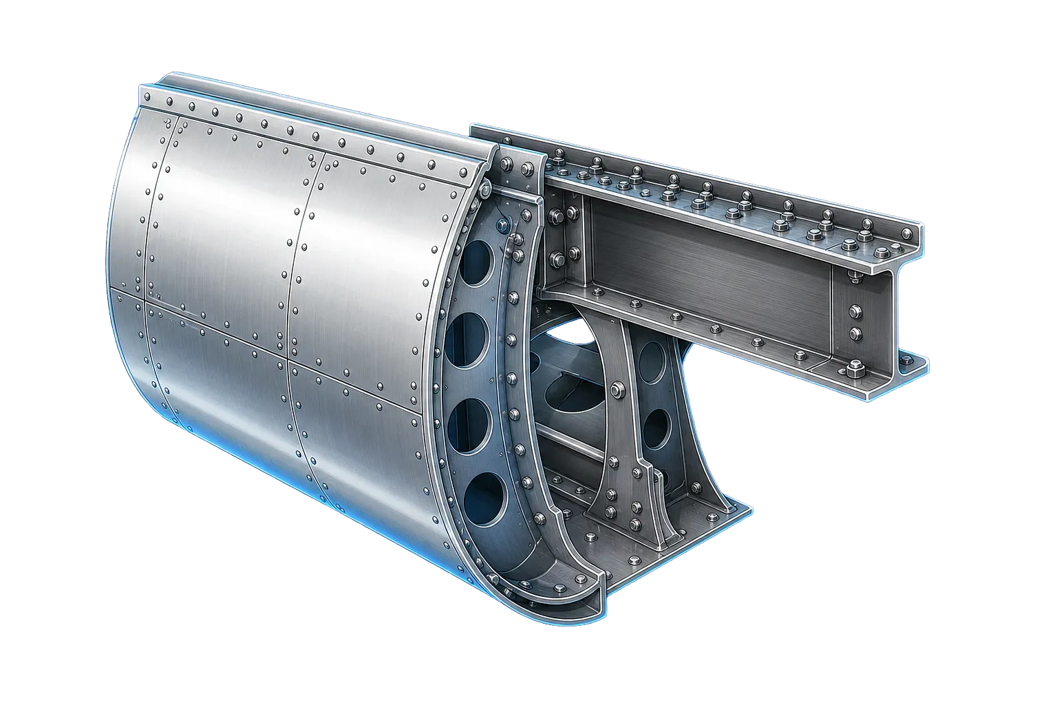
Forward Wing Spars
Applicability Source Text
Show captured applicability text from the source AD
AD Final Rules - DRS_80-21-08.html
Copy URL
Print/Save as PDF
Document Versions
 Feedback
Details
AD Number:
80-21-08
Document Type:
AD Final Rules
Docket Number:
80-ASW-42
Subject Heading:
Airworthiness Directives; Piper Model PA-25 Series Airplanes
Subject:
Forward Wing Spars
Status:
Current
Citation:
This information is not available.
Citation Publish Date:
Effective Date:
10/15/1980
Make:
Lavia Argentina S.A. (Laviasa)
Model:
PA-25 | PA-25-235 | PA-25-260
Product Type:
Aircraft
Product Subtype:
Small Airplane
Affected AD:
Superseded AD:
Affected By:
Superseded By:
Service/Office:
Office of Primary Responsibility:
CFR Part Reference:
Part 39
Comments:
AIRWORTHINESS DIRECTIVES FINAL RULES: 80-21-08
CITATION:   This information is not available.

PAGE NUMBER:

DOCKET NUMBER:   80-ASW-42

AMENDMENT:   39-3934

AD NUMBER:   80-21-08

SUBJECT HEADING:   Airworthiness Directives; Piper Model PA-25 Series Airplanes

ACTION:

SUMMARY:

DATES:   Effective October 15, 1980.

ADDRESSES:

FOR FURTHER INFORMATION CONTACT:

SUPPLEMENTARY INFORMATION:

REGULATORY TEXT:
80-21-08 PIPER: Amendment 39-3934. Applies to Model PA-25 series airplanes certificated in all categories which have incorporated STC SA501SW. (Docket No. 80-ASW-42.) Compliance required as indicated. For airplanes with forward wing spar(s) with 500 hours or more time in service since incorporation of STC SA501SW, compliance is required within 5 hours time in service after the effective date of this AD, unless already accomplished. For airplanes with forward wing spar(s) with less than 500 hours time in service since incorporation of STC SA501SW, compliance is required upon accumulation of 500 hours time in service since incorporation of STC SA501SW or within the next 5 hours time in service, whichever is later.

To detect cracks or other damage in the forward wing spar cap, accomplish the following.

(a) Remove the wing walk lower rear and lower front (leading edge) skin panels from each wing.

(b) Detach the leading edge skin panel covering the wing strut attachment to the main spar sufficiently to allow inspection of the rear flange of the lower spar cap.

(c) Visually inspect the upright, bulbed flange on the aft side of the front and rear spars (upper and lower) of both wings for misdrilled holes common to the bulbed spar flange and skin attach angles. Conduct this inspection in the areas uncovered by (a) and (b).

(1) The center unit of each fastener hole must be between .18 and .34 inches from the free end of the bulbed spar flange.

(2) A gage fabricated as shown in figure number 1 may be used to check for misdrilled holes.

(3) Figures 2 and 3 show how the gage is used.

(d) Inspect the uncovered spar caps for cracks visually and with standard dye or fluorescent penetrant inspection procedures. Place special attention to the inboard 10 inches of the front spar aft, lower cap.

(e) If misdrilled holes or cracks are found in (c) or (d), parts must be replaced with serviceable parts of the same part number. Replace blind fasteners common to the spar cap and skin angles (if removal is necessary) with MS20600M4 rivets.

(f) Visually inspect the left and right lower spar web at the inboard end for installation of the fatigue resistant doubler plates, Piper P/N 60373 and Moore/Hutcherson P/N's SPD 20025-1 and -2. The fatigue resistant doublers extend outboard of the wing-fuselage attach lug 15 inches while the original single spar web doubler extends only 6 inches outboard of the attach lug. If the fatigue resistant doubler plates are not installed, accomplish the following within the next 100 hours time in service:

(1) Remove left and right wing from fuselage.

(2) Remove wing attach fitting located on each forward wing spar root.

(3) Using standard dye or fluorescent penetrant inspection procedures, inspect the inboard end of the forward spars for a distance of 24 inches outboard of the wing-fuselage attach lug for cracks. Inspect both the spar web and the spar cap with particular attention placed on the inboard 10 inches of the rear flange of the lower spar cap.

(4) If cracks are found, part must be replaced with serviceable parts of the same part number before further flight. Replace blind fasteners common to the spar cap and skin angles (if removal is necessary) with MS20600M4 rivets.

(5) After the inspections and repair of (f)(3) and (f)(4), respectively, install the doubler plates of Moore/Hutcherson drawing SPD 20025.

(6) Reinstall the wing attach fittings and the wings.

(g) Reinstall the leading edge skin covers and walkway lower skin panels.

(h) Aircraft may be flown in accordance with FAR 21.197 to a base where inspections can be accomplished.

(i) Equivalent methods of complying with this AD may be approved by the Chief, Engineering and Manufacturing Branch, FAA, Southwest Region. This supersedes Amendment 39-1755 (38 FR 34460), AD 73-26-02, as amended by Amendment 39-1792 (39 FR 7164).

This amendment becomes effective October 15, 1980.


FIGURE NO. 1 GAGE (.06" ALUM. OR STL.)
AD 80-21-08


AD 80-21-08


AD 80-21-08


FOOTER:
Document Text
Show stored source text (verify against official source)
AD Final Rules - DRS_80-21-08.html
Copy URL
Print/Save as PDF
Document Versions
 Feedback
Details
AD Number:
80-21-08
Document Type:
AD Final Rules
Docket Number:
80-ASW-42
Subject Heading:
Airworthiness Directives; Piper Model PA-25 Series Airplanes
Subject:
Forward Wing Spars
Status:
Current
Citation:
This information is not available.
Citation Publish Date:
Effective Date:
10/15/1980
Make:
Lavia Argentina S.A. (Laviasa)
Model:
PA-25 | PA-25-235 | PA-25-260
Product Type:
Aircraft
Product Subtype:
Small Airplane
Affected AD:
Superseded AD:
Affected By:
Superseded By:
Service/Office:
Office of Primary Responsibility:
CFR Part Reference:
Part 39
Comments:
AIRWORTHINESS DIRECTIVES FINAL RULES: 80-21-08
CITATION:   This information is not available.

PAGE NUMBER:

DOCKET NUMBER:   80-ASW-42

AMENDMENT:   39-3934

AD NUMBER:   80-21-08

SUBJECT HEADING:   Airworthiness Directives; Piper Model PA-25 Series Airplanes

ACTION:

SUMMARY:

DATES:   Effective October 15, 1980.

ADDRESSES:

FOR FURTHER INFORMATION CONTACT:

SUPPLEMENTARY INFORMATION:

REGULATORY TEXT:
80-21-08 PIPER: Amendment 39-3934. Applies to Model PA-25 series airplanes certificated in all categories which have incorporated STC SA501SW. (Docket No. 80-ASW-42.) Compliance required as indicated. For airplanes with forward wing spar(s) with 500 hours or more time in service since incorporation of STC SA501SW, compliance is required within 5 hours time in service after the effective date of this AD, unless already accomplished. For airplanes with forward wing spar(s) with less than 500 hours time in service since incorporation of STC SA501SW, compliance is required upon accumulation of 500 hours time in service since incorporation of STC SA501SW or within the next 5 hours time in service, whichever is later.

To detect cracks or other damage in the forward wing spar cap, accomplish the following.

(a) Remove the wing walk lower rear and lower front (leading edge) skin panels from each wing.

(b) Detach the leading edge skin panel covering the wing strut attachment to the main spar sufficiently to allow inspection of the rear flange of the lower spar cap.

(c) Visually inspect the upright, bulbed flange on the aft side of the front and rear spars (upper and lower) of both wings for misdrilled holes common to the bulbed spar flange and skin attach angles. Conduct this inspection in the areas uncovered by (a) and (b).

(1) The center unit of each fastener hole must be between .18 and .34 inches from the free end of the bulbed spar flange.

(2) A gage fabricated as shown in figure number 1 may be used to check for misdrilled holes.

(3) Figures 2 and 3 show how the gage is used.

(d) Inspect the uncovered spar caps for cracks visually and with standard dye or fluorescent penetrant inspection procedures. Place special attention to the inboard 10 inches of the front spar aft, lower cap.

(e) If misdrilled holes or cracks are found in (c) or (d), parts must be replaced with serviceable parts of the same part number. Replace blind fasteners common to the spar cap and skin angles (if removal is necessary) with MS20600M4 rivets.

(f) Visually inspect the left and right lower spar web at the inboard end for installation of the fatigue resistant doubler plates, Piper P/N 60373 and Moore/Hutcherson P/N's SPD 20025-1 and -2. The fatigue resistant doublers extend outboard of the wing-fuselage attach lug 15 inches while the original single spar web doubler extends only 6 inches outboard of the attach lug. If the fatigue resistant doubler plates are not installed, accomplish the following within the next 100 hours time in service:

(1) Remove left and right wing from fuselage.

(2) Remove wing attach fitting located on each forward wing spar root.

(3) Using standard dye or fluorescent penetrant inspection procedures, inspect the inboard end of the forward spars for a distance of 24 inches outboard of the wing-fuselage attach lug for cracks. Inspect both the spar web and the spar cap with particular attention placed on the inboard 10 inches of the rear flange of the lower spar cap.

(4) If cracks are found, part must be replaced with serviceable parts of the same part number before further flight. Replace blind fasteners common to the spar cap and skin angles (if removal is necessary) with MS20600M4 rivets.

(5) After the inspections and repair of (f)(3) and (f)(4), respectively, install the doubler plates of Moore/Hutcherson drawing SPD 20025.

(6) Reinstall the wing attach fittings and the wings.

(g) Reinstall the leading edge skin covers and walkway lower skin panels.

(h) Aircraft may be flown in accordance with FAR 21.197 to a base where inspections can be accomplished.

(i) Equivalent methods of complying with this AD may be approved by the Chief, Engineering and Manufacturing Branch, FAA, Southwest Region. This supersedes Amendment 39-1755 (38 FR 34460), AD 73-26-02, as amended by Amendment 39-1792 (39 FR 7164).

This amendment becomes effective October 15, 1980.


FIGURE NO. 1 GAGE (.06" ALUM. OR STL.)
AD 80-21-08


AD 80-21-08


AD 80-21-08


FOOTER:
Source: Official FAA Source ↗
Retrieved: Apr 8, 2026
Rights: U.S. Government Public Domain
This site is not affiliated with or endorsed by the FAA. Always verify with official sources.
Related Airworthiness Directives
2015-08-04 Recurring
final ruleAirworthiness Directives; Various Aircraft Equipped With Wing Lift Struts
Unsafe Condition: Corrosion in wing lift struts and cracks in wing lift strut forks could lead to structural failure of the wing lift system.
2007-08-07
final ruleAirworthiness Directives; LATINOAMERICANA DE AVIACIÓN (LAVIA) S.A. (Type Certificate Data Sheets No. 2A8 and No. 2A10 Previously Held by The New Piper Aircraft, Inc.) Models PA-25, PA-25-235, and PA-25-260 Airplanes
Unsafe Condition: Severe corrosion and cracks in both rear and forward supports of the horizontal stabilizer, caused by the accumulation of steam or application products vapors.
2006-12-07
final ruleAirworthiness Directives; Engine Components Inc. (ECi) Reciprocating Engine Cylinder Assemblies
Unsafe Condition: Cracks in the cylinder assemblies and possible engine failure caused by separation of a cylinder head.

2001-23-17
final ruleAirworthiness Directives; GARMIN International GNS 430 Units
Unsafe Condition: could result in the pilot making flight decisions that put the aircraft in unsafe flight conditions.