AD 57-15-01
Applicability
| Type | Manufacturer | Model | Details |
|---|---|---|---|
| aircraft | Twin Commander Aircraft LLC | 560-A | Airworthiness Directives; Aero Commander Models 560A, 560E and 680 Aircraft |
| aircraft | Twin Commander Aircraft LLC | 560-E | Airworthiness Directives; Aero Commander Models 560A, 560E and 680 Aircraft |
| aircraft | Twin Commander Aircraft LLC | 680 | Airworthiness Directives; Aero Commander Models 560A, 560E and 680 Aircraft |
Unsafe Condition
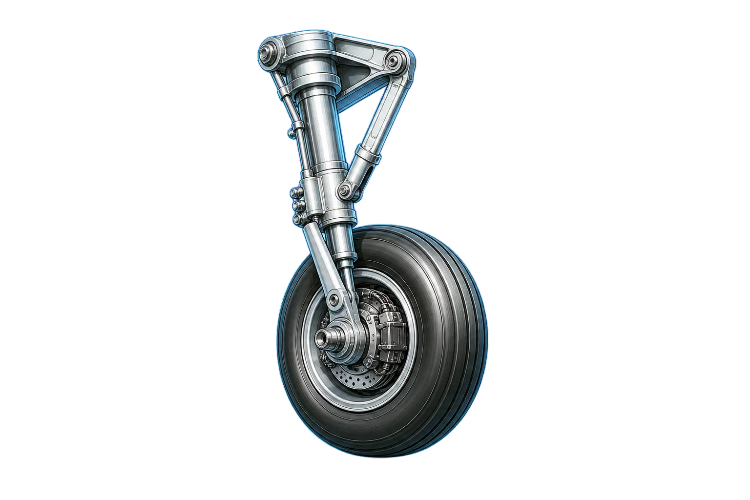
Failures have occurred on the upper retaining pins on the main landing gear, which react rebound loads when the main gear lower piston reaches its limit of extension relative to the upper cylinder.
AI-generated summary from the source AD text. Verify against the official source before acting.
Required Actions
Perform daily inspections of center scissor bolts and bushings for shearing, cracking, or elongation, and check for scissor-to-strut or scissor-to-housing contact. Replace upper bearing retaining pins immediately if any indications are found. Modify the design by installing four 3/8 inch retaining pins by October 1, 1957.
AI-generated summary from the source AD text. Verify against the official source before acting.
Compliance Time
By October 1, 1957
AI-generated summary from the source AD text. Verify against the official source before acting.
Affected Aircraft
Twin Commander Aircraft LLC models 560A, 560E, and 680, serial numbers 231 through 559.
AI-generated summary from the source AD text. Verify against the official source before acting.
Federal Register Abstract
Landing Gear Retaining Pins
Applicability Source Text
Show captured applicability text from the source AD
AD Final Rules - DRS_57-15-01.html
Copy URL
Print/Save as PDF
Document Versions
 Feedback
Details
AD Number:
57-15-01
Document Type:
AD Final Rules
Docket Number:
Unknown
Subject Heading:
Airworthiness Directives; Aero Commander Models 560A, 560E and 680 Aircraft
Subject:
Landing Gear Retaining Pins
Status:
Current
Citation:
This information is not available.
Citation Publish Date:
Effective Date:
Make:
Twin Commander Aircraft LLC
Model:
560-A | 560-E | 680
Product Type:
Aircraft
Product Subtype:
Small Airplane
Affected AD:
Superseded AD:
Affected By:
Superseded By:
Service/Office:
Office of Primary Responsibility:
CFR Part Reference:
Part 39
Comments:
AIRWORTHINESS DIRECTIVES FINAL RULES: 57-15-01
CITATION:   This information is not available.

PAGE NUMBER:

DOCKET NUMBER:   Unknown

AMENDMENT:

AD NUMBER:   57-15-01

SUBJECT HEADING:   Airworthiness Directives; Aero Commander Models 560A, 560E and 680 Aircraft

ACTION:

SUMMARY:

DATES:

ADDRESSES:

FOR FURTHER INFORMATION CONTACT:

SUPPLEMENTARY INFORMATION:

REGULATORY TEXT:
57-15-01 AERO COMMANDER: Applies to All Models 560A, 560E and 680 Serial Numbers 231 Through 559.

Compliance required as indicated.

A. Failures have occurred on the upper retaining pins on the main landing gear. These pins react the rebound loads when the main gear lower piston reaches its limit of extension with respect to the upper cylinder.

1. Until Item 2 has been accomplished the following inspections should be performed daily.

(a) With aircraft on ground remove center scissor bolts right and left main gears and inspect for evidence of shearing. These bolts normally carry zero shear load and evidence of shearing is an indication of upper bearing retaining pin failure.

(b) Inspect center scissor bushings for evidence of cracking or elongation due to shear loads being applied on center scissor bolts.

(c) Check area where scissors attach to strut and housing for evidence of scissor to strut or scissor to housing contact due to overextension of strut assembly. This is further evidence of upper bearing retaining pin failure.

If any of these indications are present, the upper bearing retaining pins must be replaced at once. Contact the Service Department, Aero Design & Engineering Co. for parts and detailed instruction to accomplish replacement.

2. To be accomplished by October 1, 1957. The present design incorporating two 1/4 inch retaining pins should be modified to incorporate four 3/8 inch retaining pins. Four pin kits and drill fixtures for installing the pins, as well as information as to where the modification can be accomplished, may be obtained from the Service Department, Aero Design & Engineering Co.

(Aero Design & Engineering Co. Service Bulletin No. 43, dated June 18, 1957, also covers this subject.)

FOOTER:
Document Text
Show stored source text (verify against official source)
AD Final Rules - DRS_57-15-01.html
Copy URL
Print/Save as PDF
Document Versions
 Feedback
Details
AD Number:
57-15-01
Document Type:
AD Final Rules
Docket Number:
Unknown
Subject Heading:
Airworthiness Directives; Aero Commander Models 560A, 560E and 680 Aircraft
Subject:
Landing Gear Retaining Pins
Status:
Current
Citation:
This information is not available.
Citation Publish Date:
Effective Date:
Make:
Twin Commander Aircraft LLC
Model:
560-A | 560-E | 680
Product Type:
Aircraft
Product Subtype:
Small Airplane
Affected AD:
Superseded AD:
Affected By:
Superseded By:
Service/Office:
Office of Primary Responsibility:
CFR Part Reference:
Part 39
Comments:
AIRWORTHINESS DIRECTIVES FINAL RULES: 57-15-01
CITATION:   This information is not available.

PAGE NUMBER:

DOCKET NUMBER:   Unknown

AMENDMENT:

AD NUMBER:   57-15-01

SUBJECT HEADING:   Airworthiness Directives; Aero Commander Models 560A, 560E and 680 Aircraft

ACTION:

SUMMARY:

DATES:

ADDRESSES:

FOR FURTHER INFORMATION CONTACT:

SUPPLEMENTARY INFORMATION:

REGULATORY TEXT:
57-15-01 AERO COMMANDER: Applies to All Models 560A, 560E and 680 Serial Numbers 231 Through 559.

Compliance required as indicated.

A. Failures have occurred on the upper retaining pins on the main landing gear. These pins react the rebound loads when the main gear lower piston reaches its limit of extension with respect to the upper cylinder.

1. Until Item 2 has been accomplished the following inspections should be performed daily.

(a) With aircraft on ground remove center scissor bolts right and left main gears and inspect for evidence of shearing. These bolts normally carry zero shear load and evidence of shearing is an indication of upper bearing retaining pin failure.

(b) Inspect center scissor bushings for evidence of cracking or elongation due to shear loads being applied on center scissor bolts.

(c) Check area where scissors attach to strut and housing for evidence of scissor to strut or scissor to housing contact due to overextension of strut assembly. This is further evidence of upper bearing retaining pin failure.

If any of these indications are present, the upper bearing retaining pins must be replaced at once. Contact the Service Department, Aero Design & Engineering Co. for parts and detailed instruction to accomplish replacement.

2. To be accomplished by October 1, 1957. The present design incorporating two 1/4 inch retaining pins should be modified to incorporate four 3/8 inch retaining pins. Four pin kits and drill fixtures for installing the pins, as well as information as to where the modification can be accomplished, may be obtained from the Service Department, Aero Design & Engineering Co.

(Aero Design & Engineering Co. Service Bulletin No. 43, dated June 18, 1957, also covers this subject.)

FOOTER:
Source: Official FAA Source ↗
Retrieved: Apr 8, 2026
Rights: U.S. Government Public Domain
This site is not affiliated with or endorsed by the FAA. Always verify with official sources.
Related Airworthiness Directives
2023-09-09 Recurring
final ruleAirworthiness Directives; Various Airplanes, Helicopters, and Engines
Unsafe Condition: Multiple failures of spot-welded, multi-segment v-band couplings at the tailpipe to the turbocharger exhaust housing flange.
2005-18-20
final ruleAirworthiness Directives; Goodrich De-icing and Specialty Systems “FASTprop” Propeller De-icers
Unsafe Condition: Goodrich De-icing and Specialty Systems 'FASTprop' propeller de-icers becoming loose or debonded, and detaching from propeller blades during operation.
2005-01-19
final ruleAirworthiness Directives; GARMIN International Inc. GTX 33, GTX 33D, GTX 330, and GTX 330D Mode S Transponders
Unsafe Condition: The GTX 33/33D/330/330D Mode S transponders may detect the S1 (suppression) interrogating pulse below the minimum trigger level (MTL) and, in some circumstances, not reply. This could lead to inacc...
98-20-34
final ruleAirworthiness Directives; Twin Commander Aircraft Corporation Models 500, 500-A, 500-B, 500-S, 500-U, 520, 560, 560-A, 560-E, 560-F, 680, 680-E, 680FL(P), 680T, 680V, 680W, 681, 685, 690, 690A, 690B, 690C, 690D, 695, 695A, 695B, and 720 Airplanes.
Unsafe Condition: Airplane Flight Manuals--Severe Icing Conditions